| |

Verilog TutorialVerilog is a Hardware Description Language (HDL). It is a language used for describing a digital system such as a network switch, a microprocessor, a memory, or a flip-flop. We can describe any digital hardware by using HDL at any level. Designs described in HDL are independent of technology, very easy for designing and debugging, and are normally more useful than schematics, particularly for large circuits. What is Verilog?Verilog is a HARDWARE DESCRIPTION LANGUAGE (HDL), which is used to describe a digital system such as a network switch or a microprocessor or a memory a flip-flop. 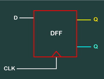
Verilog was developed to simplify the process and make the HDL more robust and flexible. Today, Verilog is the most popular HDL used and practiced throughout the semiconductor industry. HDL was developed to enhance the design process by allowing engineers to describe the desired hardware's functionality and let automation tools convert that behavior into actual hardware elements like combinational gates and sequential logic. Verilog is like any other hardware description language. It permits the designers to design the designs in either Bottom-up or Top-down methodology.
Verilog Abstraction LevelsVerilog supports a design at many levels of abstraction, such as:
Behavioral levelThe behavioral level describes a system by concurrent algorithms behavioral. Every algorithm is sequential, which means it consists of a set of executed instructions one by one. Functions, tasks, and blocks are the main elements. There is no regard for the structural realization of the design. Register-Transfer LevelDesigns using the Register-Transfer Level specify a circuit's characteristics using operations and the transfer of data between the registers. The modern definition of an RTL code is "Any code that is synthesizable is called RTL code". Gate LevelThe characteristics of a system are described by logical links and their timing properties within the logical level. All signals are discrete signals. They can only have definite logical values (`0', `1', `X', `Z`). The usable operations are predefined logic primitives (basic gates). Gate level modeling may not be the right idea for logic design. Gate level code is generated using tools such as synthesis tools, and his netlist is used for gate-level simulation and backend. History of Verilog
How is Verilog useful?Verilog creates a level of abstraction that helps hide away the details of its implementation and technology. For example, a D flip-flop design would require the knowledge of how the transistors need to be arranged to achieve a positive-edge triggered FF and what the rise, fall, and CLK-Q times required to latch the value onto a flop among much other technology-oriented details. Power dissipation, timing, and the ability to drive nets and other flops would also require a more thorough understanding of a transistor's physical characteristics. Verilog helps us to focus on the behavior and leave the rest to be sorted out later. PrerequisitesBefore learning Verilog, you should have a basic knowledge of VLSI Design language.
AudienceOur Verilog tutorial is designed to help beginners, Design Engineers, and Verification Engineers who are willing to learn how to model digital systems in the Verilog HDL to allow for automatic synthesis. By the end of this tutorial, you will have gained an intermediate level of expertise in Verilog. ProblemWe assure you that you will not find any problem with the Verilog Tutorial. But if there is any mistake, please post the question in the contact form.
Next TopicLexical Tokens
|
 For Videos Join Our Youtube Channel: Join Now
Feedback
- Send your Feedback to [email protected]
Help Others, Please Share


Javatpoint Services
JavaTpoint offers too many high quality services. Mail us on [email protected], to get more information about given services.
- Website Designing
- Website Development
- Java Development
- PHP Development
- WordPress
- Graphic Designing
- Logo
- Digital Marketing
- On Page and Off Page SEO
- PPC
- Content Development
- Corporate Training
- Classroom and Online Training
- Data Entry
Training For College Campus
JavaTpoint offers college campus training on Core Java, Advance Java, .Net, Android, Hadoop, PHP, Web Technology and Python. Please mail your requirement at [email protected]
Duration: 1 week to 2 week


