| |

PCM (Pulse Code Modulation)Modulation is a process where different parameter (amplitude, frequency, and phase) of a carrier signal varies with the instantaneous value of the message signal. A carrier signal is a high-frequency signal, and the message signal is the original signal transmitted from the transmitter to the receiver. The message signal carries the information from one place to the other. The carrier signal is used with the message signal to make it suitable for long-distance transmission. Different modulation techniques use different parameters to transmit a signal from the transmitter to the receiver. Here, we will discuss the PCM (Pulse Code Modulation) technique, one of the digital modulation methods to transmit the signal. A PCM system converts an analog input signal to the digital signal, which is a combination of the binary sequence created from the binary digits 0 and 1. An analog signal is a continuous wave, and the PCM signal is a wave with a series of digits. Thus, we can define PCM as the modulation method that transmits the pulses in the form of binary digits representing a code number. A simple diagram of the analog waveform and the corresponding PCM waveform is shown below: Electrical representation of the PCM signalThe signals are transmitted in the electrical form from the transmitter to the receiver. It is due to the dependence of electronic devices on the electric current for its operation. The binary digits are represented in the form of electric pulses to transmit the code over a communication channel. A simple diagram of the binary digits represented in the form of electric pulses is shown below: 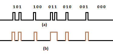
A binary digit '0' indicates the absence of a pulse, and the binary digits '1' indicates the presence of a pulse. The above diagram shows the sequence of three digits that depicts the binary number from 0 to 5. The first sequence (a) of digital pulses is the PCM waveform transmitted to the receiver as the sequence of the quantized samples. The second sequence (b) is the alternative method to represent the digital pulses. The three digits sequence representing a decimal number in the binary form specifies a sampled value called word. The space between the two adjacent words helps in the easy multiplexing and demultiplexing of the signals. At the receiver end, the pulse's presence and absence help us determine the binary digits of the coded signal. The amplitude of the pulse in detecting the binary digits is not important. The wide pulse width easily allows recognizing the pulse against the noise. A rising pulse indicates a digit' 1' and the lower level pulse indicate a digit' 0.' PCM systemA communication system contains a transmitter, channel, and receiver. A transmitter and a receiver have various components depending on the input signal and the output requirements. It performs two functions, modulation and demodulation. Modulation sends the message signal with the carrier signal, which helps in enhancing the signals' characteristics. It also removes any noise, interference, or distortion in the signal. The demodulation process recovers the original signal to make it suitable for the receiver. A signal is sampled and quantized before transmission. It allows us to perform TDM (Time Division Multiplexing) and reduce the effects of noise. The combined sampling and quantization operation produces a digital PAM (Pulse Amplitude Modulation) signal, where the amplitude of the pulse varies with the instantaneous value of the message signal. We can either transmit these values directly or uses the coding method to transmit the code rather than the value. The code number is represented in binary form before transmission. Such as, the method of transmission is performed using the PCM system. The block diagram of the Pulse Code Modulation system is shown below: 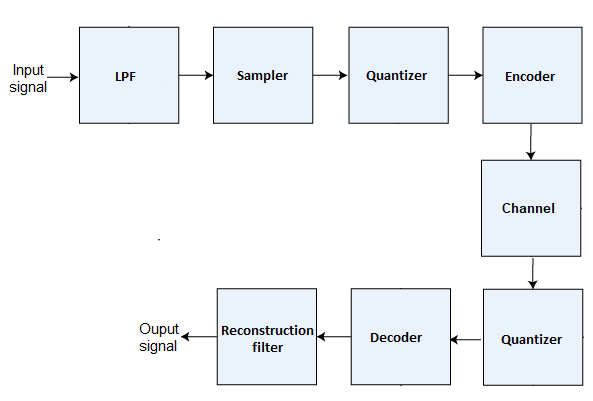
The components of a PCM system are a low pass filter, sampler, quantizer, encoder, communication channel, quantizer, decoder, and a reconstruction filter. The input message signal m(t) is the analog signal applied to the sampler. The combination of quantizer and encoder is known as ADC (Analog to Digital Converter). The A/D converter replaces the analog signal with the code symbols, where each symbol represents the train of pulses interpreted as the binary digits. The first quantizer is present at the transmitting end, while the second quantizer is present at the receiving end. The signal transmitted through the Pulse Code Modulation system is also referred a digitally encoded signal. Let's discuss the components of PCM system in detail. LPFAs the name implies, a filter passes a certain range of frequencies and reject the other. A Low Pass Filter (LPF) rejects the higher frequencies from the input signal and passes the other frequencies, specified by the filter. It is done to avoid any aliasing or distortion in the input signal. SamplerSampling refers to the process of measuring the instantaneous value of the continuous signal is the discrete form. The input signal of the PCM system is analog, which is a continuous time-varying signal. The analog signal passes through the sampler, where it is sampled periodically. The sampler measures the instantaneous value of the analog signal, converts it to the discrete symbols and sends it to the quantizer. QuantizerAfter passing through the sampler, the samples are subjected to quantization operation. It reduces the number of discreet symbols. The quantizer performs the process of data compression and data redundancy. It adds some redundant bits and compresses the data to make it suitable for storage and transmission. EncoderAn encoder is a device that converts the analog signal to digital pulses. It responds to each sample by generating a binary pulse or pattern. The combination of Low pass filter, quantizer, and encoder works as an A/D or Analog to Digital Converter. It also reduces the transmission bandwidth. Communication channelA communication channel is a medium between the transmitter and the receiver. It transmits a PCM signal from the transmitter to the receiver. It also includes a repeater that can regenerate the signal, improve signal strength, and reduce noise effects. The PCM system, including a regenerative repeater, is shown below: 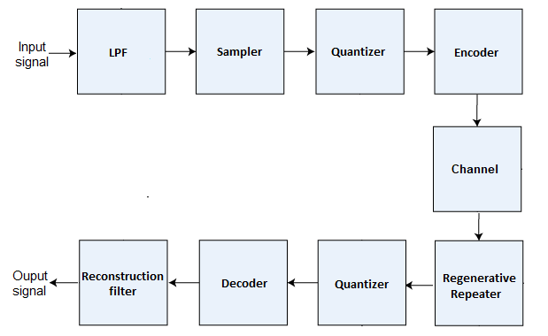
QuantizerThe quantizer decides whether the received pulse is positive or negative. According to the decision, it regenerates the pulse train and sends it to the decoder. The quantizer first quantizes the samples pulses at the transmitting stage. The quantization process for the second quantizer now becomes easy. It needs only to detect the arrival of the digital pulses. It is easy for the quantizer to detect the code in the form of binary numbers that contains only two digits, 0 and 1. The process becomes complicated when the quantized samples from the first quantizer are directly sent to the second quantizer. It then needs to detect a level from the multiple levels (0 to 7). If a repeater is used, it simply raises the level of the regenerated pulse and is sent to the other block of the communication system. DecoderThe digitally encoded signal arrives at the receiver. It first removes the noise from the signal. The quantization process does not allow the easy separation of the signal and the noise. Hence, it is essential to remove the noise from the signal at the decoding stage. It works similar to the demodulation process and converts the binary pulses to the original form or the analog signal. Reconstruction FilterThe reconstruction filter, decoder, and quantizer work together as a D/A (Digital to Analog Converter). A reconstruction filter helps in the smooth conversion of the digital signal back to the original analog signal. Thus, we can conclude that PCM system converts the analog signal to the digital signal, removes the noise, and converts it back to the analog signal as the output. Function of the PCM systemWe have discussed all the components of a PCM system. Let's discuss the function of a PCM system with the help of an example of an audio signal. The audio signal is first applied to the low-pass filter, which rejects the higher range of frequencies from the signal. The sampler performs the sampling of the left and right channels of the audio signal based on the sampling rate of 44100 Hz or 44.1k Hz and 16/32-bit resolution. The quantizer and encoder set the digital value based on the specified resolution and bit rate and send it to the receiver. The digital signal passes through the quantizer that generates the pulse according to the received positive or negative pulse. The decoder converts the regenerated pulse back to the analog signal. Further, it sends to the reconstruction filter, which helps in the smooth conversion of the digital signal back to the original analog signal. Coding process related to PCMVarious forms of PCM processes are used in coding and signal processing in communication. Let's discuss some of the most common coding processes related to the Pulse Code Modulation.
We will discuss all these coding processes later in this tutorial. Advantages of PCMThe advantages of Pulse Code Modulation are as follows:
Disadvantages of PCMThe disadvantages of Pulse Code Modulation are as follows:
Applications of PCMThere are various applications of PCM. Let's discuss some of its most common applications.
Next TopicQuantization
|
 For Videos Join Our Youtube Channel: Join Now
Feedback
- Send your Feedback to [email protected]
Help Others, Please Share


Javatpoint Services
JavaTpoint offers too many high quality services. Mail us on [email protected], to get more information about given services.
- Website Designing
- Website Development
- Java Development
- PHP Development
- WordPress
- Graphic Designing
- Logo
- Digital Marketing
- On Page and Off Page SEO
- PPC
- Content Development
- Corporate Training
- Classroom and Online Training
- Data Entry
Training For College Campus
JavaTpoint offers college campus training on Core Java, Advance Java, .Net, Android, Hadoop, PHP, Web Technology and Python. Please mail your requirement at [email protected]
Duration: 1 week to 2 week


