| |

Pulse Time Modulation (PTM)PTM involves pulse train and sampling on the time axis of the signal. We can also define it as a modulation technique of time intervals between the successive pulse of constant amplitude and duration. PTM is a combination of PWM (Pulse Width Modulation) and PPM (Pulse Position Modulation). The modulation and demodulation of both types of PTM are closely related. PPM is generated with the help of PWM input. But, the randomness in both the modulation does not make it suitable for the TDM (Time Division Multiplexing). It makes their contribution to the communication process very small. PWM (Pulse Width Modulation)As the name implies, PWM is the modulation based on the regulation of the width of the pulse PWM involves pulse train and sampling. Here, the message modulates the width of the pulse. The applications of PWM include motor control and power delivery, controlled by regulating the pulse width. PWM pulse occurs at regular intervals. The block diagram of PWM is shown below: 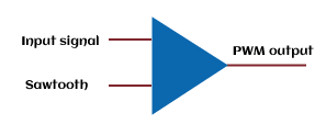
The first block is the comparator block, which has two inputs, inverting and non-inverting. The first input is the message signal and the second input of the comparator is the sawtooth signal. The purpose of selecting the sawtooth signal is its operating frequency, equal to the carrier frequency. The maximum of the input signal should be less than that of the sawtooth signal. We get the desired PWM signal at the output if this condition is satisfied. The wave diagram of PWM is shown below: 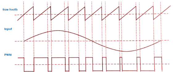
The above graph shows that the rising edge of PWM and the falling edge of the sawtooth signal coincides with each other. When the sawtooth edge is less than the input signal, the positive input of the comparator goes high, and we get the positive output. If the sawtooth edge is greater than the input signal, the negative input of the comparator goes high, and we get the negative output. The sawtooth is connected at the inverting (-) input. If the input at the inverting terminal is high compared to the non-inverting (+) input, the output will also be negative. The width of the pulse depends on the magnitude of the input signal. It also decides the duration for which the output of the comparator goes high. Demodulation of PWMDemodulation is a process to recover the original signal. It is opposite to the modulation process. The demodulation of pulse modulation techniques (PWM, PPM, and PAM) is quite easy compared to other modulation types. In PWM, a ramp signal is taken starting at the positive edge. It is stopped when the negative edge comes. The width of the ramp signal is different and thus follows different heights depending on the amplitude and width of the pulse. When it passes through the LPF (Low Pass Filter), it forms an envelope and appears as the demodulated signal at the output. RC (Resistor and Capacitor) combinations and transistors can be used to generate the ramp signal. Advantages of PWMThe advantages of Pulse Width Modulation are as follows:
Disadvantages of PWMThe disadvantages of Pulse Width Modulation are as follows:
PPM (Pulse Position Modulation)It also involves pulse train and sampling like PWM. Here, the arrival position of the fixed-width pulse in each sample period is modulated by the message signal. The block diagram of PPM is shown below: 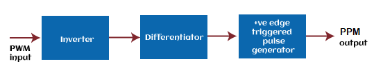
The PWM generated signal is applied to the inverter, which reverses the polarity of the input signal. For the positive input pulse, it converts it into the negative pulse and for the negative input pulse; it converts the polarity into the positive pulse. The output of the inverter is fed to the differentiator. It generates positive spikes when the PWM output pulse goes from HIGH to LOW. Similarly, it generates negative spikes when the PWM pulse goes from LOW to HIGH. These spikes are further applied to the positive edge triggered pulse generator, which generates the pulse only when the positive spike appears. It means that it does not produce the pulse during the negative spikes. The output waves are shown below: 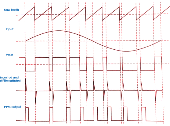
The PPM output depicts the output only in the form of a positive pulse. It is due to a positive edge-triggered pulse generator, as discussed above. The positive spikes at the PPM output coincide with the PWM signal's falling edge. The position of pulses carries the information in the Pulse Position Modulation. It is a direct method to generate the PPM signal. In the case of the indirect method, the sawtooth signal is added to the PAM signal. The comparator further performs the slicing actions. The width of the pulse will be directly proportional to the amplitude of the signal. The greater the amplitude, the greater will be the pulse width. Demodulation of PPMIn PPM, the demodulation is performed using the edge triggered flip-flop, as shown below: 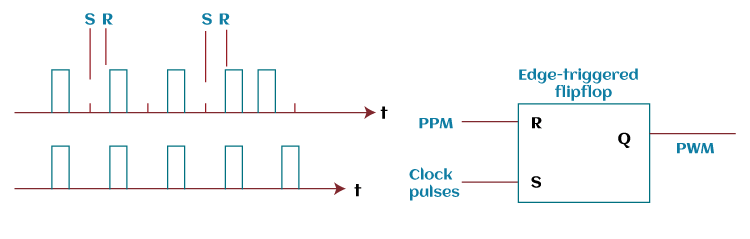
The output of the flip-flop is the train of pulses in the set and reset position at every clock pulse. There are two inputs of the flip-flop, R and S. The positive clock is set at the S input of the flip-flop. It is kept at high to keep the output at high until a positive edge from the PPM resets it. The pulse width at the output depends on the PPM and the width of the amplitude. Thus, we get the PWM signal at the output of the flip-flop. We can also demodulate the signal using a similar process as discussed in PWM demodulation. A ramp signal is taken starting at the positive edge. It is stopped when the other end of the positive edge comes. The height of the ramp depends on the delay between the two positive pulses. When it passes through the LPF (Low Pass Filter), it appears as the demodulated signal at the output. Here also, RC (Resistor and Capacitor) combinations and transistors can be used to generate the ramp signal. Advantages of PPMThe advantages of Pulse Position Modulation are as follows:
Disadvantages of PPMThe disadvantages of Pulse Position Modulation are as follows:
Next TopicRadio receiver
|
 For Videos Join Our Youtube Channel: Join Now
Feedback
- Send your Feedback to [email protected]
Help Others, Please Share


Javatpoint Services
JavaTpoint offers too many high quality services. Mail us on [email protected], to get more information about given services.
- Website Designing
- Website Development
- Java Development
- PHP Development
- WordPress
- Graphic Designing
- Logo
- Digital Marketing
- On Page and Off Page SEO
- PPC
- Content Development
- Corporate Training
- Classroom and Online Training
- Data Entry
Training For College Campus
JavaTpoint offers college campus training on Core Java, Advance Java, .Net, Android, Hadoop, PHP, Web Technology and Python. Please mail your requirement at [email protected]
Duration: 1 week to 2 week


