| |

Arduino Coding BasicsWe have already discussed the popular Arduino Boards, Arduino IDEs, and Installation process of the Arduino software. We learned that Arduino IDE (Integrated Development Environment) allows us to draw the sketch and upload it to the various Arduino boards using code. The code is written in a simple programming language similar to C and C++. The initial step to start with Arduino is the IDE download and installation. Let's discuss the basics to start with Arduino programming. BracketsThere are two types of brackets used in the Arduino coding, which are listed below:
Parentheses ( ) The parentheses brackets are the group of the arguments, such as method, function, or a code statement. These are also used to group the math equations. Curly Brackets { } The statements in the code are enclosed in the curly brackets. We always require closed curly brackets to match the open curly bracket in the code or sketch. Open curly bracket- ' { ' Closed curly bracket - ' } ' Line CommentThere are two types of line comments, which are listed below:
// Single line comment The text that is written after the two forward slashes are considered as a single line comment. The compiler ignores the code written after the two forward slashes. The comment will not be displayed in the output. Such text is specified for a better understanding of the code or for the explanation of any code statement. The // (two forward slashes) are also used to ignore some extra lines of code without deleting it. / * Multi - line comment */ The Multi-line comment is written to group the information for clear understanding. It starts with the single forward slash and an asterisk symbol (/ *). It also ends with the / *. It is commonly used to write the larger text. It is a comment, which is also ignored by the compiler. Coding ScreenThe coding screen is divided into two blocks. The setup is considered as the preparation block, while the loop is considered as the execution block. It is shown below: 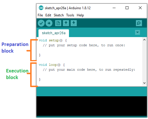
The set of statements in the setup and loop blocks are enclosed with the curly brackets. We can write multiple statements depending on the coding requirements for a particular project. For example: What is Setup? What type of code is written in the setup block? It contains an initial part of the code to be executed. The pin modes, libraries, variables, etc., are initialized in the setup section. It is executed only once during the uploading of the program and after reset or power up of the Arduino board. Zero setup () resides at the top of each sketch. As soon as the program starts running, the code inside the curly bracket is executed in the setup and it executes only once. What is Loop? What type of code is written in the Loop block? The loop contains statements that are executed repeatedly. The section of code inside the curly brackets is repeated depending on the value of variables. Time in ArduinoThe time in Arduino programming is measured in a millisecond. Where, 1 sec = 1000 milliseconds We can adjust the timing according to the milliseconds. For example, for a 5-second delay, the time displayed will be 5000 milliseconds. Example: Let's consider a simple LED blink example. The steps to open such example are:
The example will reopen in a new window, as shown below: 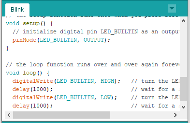
pinMode ( )The specific pin number is set as the INPUT or OUTPUT in the pinMode () function. The Syntax is: pinMode (pin, mode) Where, pin: It is the pin number. We can select the pin number according to the requirements. Mode: We can set the mode as INPUT or OUTPUT according to the corresponding pin number. Let' understand the pinMode with an example. Example: We want to set the 12 pin number as the output pin. Code: Why is it recommended to set the mode of pins as OUTPUT? The OUTPUT mode of a specific pin number provides a considerable amount of current to other circuits, which is enough to run a sensor or to light the LED brightly. The output state of a pin is considered as the low-impedance state. The high current and short circuit of a pin can damage the ATmel chip. So, it is recommended to set the mode as OUTPUT. Can we set the pinMode as INPUT? The digitalWrite () will disable the LOW during the INPUT mode. The output pin will be considered as HIGH. We can use the INPUT mode to use the external pull-down resistor. We are required to set the pinMode as INPUT_PULLUP. It is used to reverse the nature of the INPUT mode. The sufficient amount of current is provided by the pull-up mode to dimly light an LED, which is connected to the pin in the INPUT mode. If the LED is working dimly, it means this condition is working out. Due to this, it is recommended to set the pin in OUTPUT mode.
digitalWrite( )The digitalWrite ( ) function is used to set the value of a pin as HIGH or LOW. Where, HIGH: It sets the value of the voltage. For the 5V board, it will set the value of 5V, while for 3.3V, it will set the value of 3.3V. LOW: It sets the value = 0 (GND). If we do not set the pinMode as OUTPUT, the LED may light dim. The syntax is: digitalWrite( pin, value HIGH/LOW) pin: We can specify the pin number or the declared variable. Let's understand with an example. Example: The HIGH will ON the LED and LOW will OFF the LED connected to pin number 13. What is the difference between digitalRead () and digitalWrite ()? The digitalRead () function will read the HIGH/LOW value from the digital pin, and the digitalWrite () function is used to set the HIGH/LOW value of the digital pin. delay ( )The delay () function is a blocking function to pause a program from doing a task during the specified duration in milliseconds. For example, - delay (2000) Where, 1 sec = 1000millisecond Hence, it will provide a delay of 2 seconds. Code: Here, the LED connected to pin number 13 will be ON for 2 seconds and OFF for 1 second. The task will repeatedly execute as it is in the void loop (). We can set the duration according to our choice or project requirements. Example: To light the LED connected to pin number 13. We want to ON the LED for 4 seconds and OFF the LED for 1.5 seconds. Code:
Next TopicSyntax & Program Flow
|
 For Videos Join Our Youtube Channel: Join Now
Feedback
- Send your Feedback to [email protected]
Help Others, Please Share


Javatpoint Services
JavaTpoint offers too many high quality services. Mail us on [email protected], to get more information about given services.
- Website Designing
- Website Development
- Java Development
- PHP Development
- WordPress
- Graphic Designing
- Logo
- Digital Marketing
- On Page and Off Page SEO
- PPC
- Content Development
- Corporate Training
- Classroom and Online Training
- Data Entry
Training For College Campus
JavaTpoint offers college campus training on Core Java, Advance Java, .Net, Android, Hadoop, PHP, Web Technology and Python. Please mail your requirement at [email protected]
Duration: 1 week to 2 week


