| |

Limits CommandThe Limits command in AutoCAD is used to set an invisible rectangular boundary in the drawing area or viewport. It limits the grid display and the point locations. We are required to specify the coordinates of the opposite corners of the rectangular window. The opposite corners are named as Upper right and Lower left corners. The opposite corners are shown in the below image: 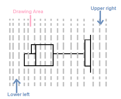
Why we need limits? Some dimensions in a drawing are represented in hundreds and thousands of meters. For example, bridge designing in AutoCAD, Architecture designing, etc. The representation of such large dimensions is difficult in a regular drawing area. For such purposes, limits play a vital role in setting the boundary of the drawing area. We can specify the limits according to our requirements. Limits CheckingThe two options under limits checking are:
Steps to set the limitsThe steps to set the limits are listed below:
The Z and E are mandatory to activate the limits. It is also called a regenerating mode of limits. Now, we can quickly create drawings within the dimensions mentioned above. Note: The dimensions of a figure should be within the specified limits. If it is greater, we can re-specify the limits according to the requirements.Let's understand limits with few examples. Example 1: Draw a rectangle of dimension 100 x 200. Here, the length of the rectangle is 100, and the width is 200. The steps are listed below:
Using above steps, the rectangle will be created. Example 2: Draw two adjacent squares of side 200. The gap between the squares should be 50. The length of the figure will be 200 (side of square1) + 50 (gap) +200 (side of square2) = 450. So, we will specify the limits greater than the dimensions of the figure. The steps are listed below:
The figure will be created, as shown in the below image: 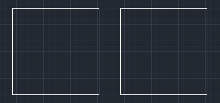
Next TopicErase in AutoCAD
|
 For Videos Join Our Youtube Channel: Join Now
Feedback
- Send your Feedback to [email protected]
Help Others, Please Share


Javatpoint Services
JavaTpoint offers too many high quality services. Mail us on [email protected], to get more information about given services.
- Website Designing
- Website Development
- Java Development
- PHP Development
- WordPress
- Graphic Designing
- Logo
- Digital Marketing
- On Page and Off Page SEO
- PPC
- Content Development
- Corporate Training
- Classroom and Online Training
- Data Entry
Training For College Campus
JavaTpoint offers college campus training on Core Java, Advance Java, .Net, Android, Hadoop, PHP, Web Technology and Python. Please mail your requirement at [email protected]
Duration: 1 week to 2 week


